Tuesday, January 12, 2021

Static route with Next-hop or exit interface comparative drive.

Specifying A Next-Hop IP Address


 In order to insert a static default route into the routing table, ip route 0.0.0.0 0.0.0.0 155.0.0.7 is configured.

 R9#show ip route
 Gateway of last resort is 155.0.0.7 to network 0.0.0.0
 S*    0.0.0.0/0 [1/0] via 155.0.0.7
      155.0.0.0/16 is variably subnetted, 2 subnets, 2 masks
C        155.0.0.0/24 is directly connected, GigabitEthernet1
L        155.0.0.9/32 is directly connected, GigabitEthernet1 

I wrote a simple TCL script to ping the remote destinations at once.

R9#tclsh
R9(tcl)#foreach n {
+>(tcl)#155.1.1.1
+>(tcl)#155.2.2.2
+>(tcl)#155.3.3.3
+>(tcl)#155.4.4.4
+>(tcl)#} { ping $n } 
Sending 5, 100-byte ICMP Echos to 155.1.1.1, timeout is 2 seconds:
!!!!!
Success rate is 100 percent (5/5), round-trip min/avg/max = 1/1/1 ms
 Sending 5, 100-byte ICMP Echos to 155.2.2.2, timeout is 2 seconds:
!!!!!
Success rate is 100 percent (5/5), round-trip min/avg/max = 1/1/1 ms
 Sending 5, 100-byte ICMP Echos to 155.3.3.3, timeout is 2 seconds:
!!!!!
Success rate is 100 percent (5/5), round-trip min/avg/max = 1/1/1 ms
 Sending 5, 100-byte ICMP Echos to 155.4.4.4, timeout is 2 seconds:
!!!!!
Success rate is 100 percent (5/5), round-trip min/avg/max = 1/1/1 ms

Evidently, the pings are successful, but let’s view the lookup process in more detail.

First, R9 must generate an ARP Request to find the MAC address of its next-hop neighbor R7. The ARP Request contains the following information: src IP = 155.0.0.9, scr MAC = 000c.2999.fcba, dst IP = 155.0.0.7, and dst MAC = 0000.0000.0000 (unknown). R7 sends back an ARP Reply with src IP = 155.0.0.7, src MAC = 000c.2968.22dd, dst IP = 155.0.0.9, and dst MAC = 000c.2999.fcba.

R9#debug arp
IP ARP: sent req src 155.0.0.9 000c.2999.fcba,
                 dst 155.0.0.7 0000.0000.0000 GigabitEthernet1
IP ARP: rcvd rep src 155.0.0.7 000c.2968.22dd, dst 155.0.0.9 GigabitEthernet1

Notice that the ARP cache contains only a single dynamically learned entry (R7). In fact, this is the only required information, because from R9’s perspective all remote destinations are reached through R7. R9 is effectively saying: “All packets that do not have a more specific entry in the routing table are forwarded to R7, so I will address my Layer 2 frames to him accordingly.”

R9#show arp
Protocol  Address          Age (min)  Hardware Addr   Type   Interface
Internet  155.0.0.7               0   000c.2968.22dd  ARPA   GigabitEthernet1
Internet  155.0.0.9               -   000c.2999.fcba  ARPA   GigabitEthernet1

 Specifying An Exit Interface

 The previous chapter proved that pointing a static default route to a next-hop IP is an effective solution, requiring minimal memory resources and processing cycles to reconstruct the Layer 2 header. By contrast, pointing a route to an exit interface can potentially cause high processor utilization and a very large ARP cache (along with attendant memory allocation failures).

 R9(config)#ip route 0.0.0.0 0.0.0.0 GigabitEthernet1 
When a static route is associated with an exit interface, it shows up in the routing table as directly connected.
 R9#show ip route
 Gateway of last resort is 0.0.0.0 to network 0.0.0.0
 S*    0.0.0.0/0 is directly connected, GigabitEthernet1
      155.0.0.0/16 is variably subnetted, 2 subnets, 2 masks
C        155.0.0.0/24 is directly connected, GigabitEthernet1
L        155.0.0.9/32 is directly connected, GigabitEthernet1

Now, directly connected implies Layer 2 neighborship, which causes the router to consider each destination within the range of the route to be directly reached through that interface. So, instead of resolving to a
single next-hop IP address, the router must find the Layer 2 information for each unique destination.
 If I issued the TCL script again, the pings would continue to fly successfully (omitting the lengthy output, you’ll just have to believe me). But what happens under the hood? The router is generating ARP requests for all destinations separately.

R7#debug arp
IP ARP: rcvd req src 155.0.0.9 000c.2999.fcba, dst 155.1.1.1 GigabitEthernet1
IP ARP: rcvd req src 155.0.0.9 000c.2999.fcba, dst 155.2.2.2 GigabitEthernet1
IP ARP: rcvd req src 155.0.0.9 000c.2999.fcba, dst 155.3.3.3 GigabitEthernet1
IP ARP: rcvd req src 155.0.0.9 000c.2999.fcba, dst 155.4.4.4 GigabitEthernet1

Wait.. If the router sends an ARP request for the final destination, which is not actually directly connected, then how does the packet reach its intended recipient? Simple: proxy ARP. Today, the use of proxy ARP is not that common. In fact, it is often a "quick fix" for potential routing issues. Proxy ARP uses the exact same process as ARP, except the ARP request is requesting a MAC address that is not on the local subnet. If a router has a route to the requested destination, it can issue a proxy ARP reply with its own MAC address on behalf of the target host. The following figure demonstrates the concept.


Notice that R7 replies to the received ARP requests by sending back its interface GigabitEthernet1 MAC address.

R7#show interface GigabitEthernet1
GigabitEthernet1 is up, line protocol is up
  Hardware is CSR vNIC, address is 000c.2968.22dd (bia 000c.2968.22dd)
  Internet address is 155.0.0.7/24

R7#debug arp
IP ARP: sent rep src 155.1.1.1 000c.2968.22dd,
                 dst 155.0.0.9 000c.2999.fcba GigabitEthernet1
IP ARP: sent rep src 155.2.2.2 000c.2968.22dd,
                 dst 155.0.0.9 000c.2999.fcba GigabitEthernet1
IP ARP: sent rep src 155.3.3.3 000c.2968.22dd,
                 dst 155.0.0.9 000c.2999.fcba GigabitEthernet1
IP ARP: sent rep src 155.4.4.4 000c.2968.22dd,
                 dst 155.0.0.9 000c.2999.fcba GigabitEthernet1
 
R7#show ip interface GigabitEthernet1
GigabitEthernet1 is up, line protocol is up
  Internet address is 155.0.0.7/24
  Broadcast address is 255.255.255.255
  Proxy ARP is enabled

The ARP cache on R9 has grown considerably larger. Also notice that all entries are essentially identical, mapped to the same hardware address. In a lab environment, these effects of a larger ARP table and higher CPU utilization are minimal but in a high-volume production network potentially devastating consequences may result.

R9#show arp
Protocol  Address          Age (min)  Hardware Addr   Type   Interface
Internet  155.1.1.1               0   000c.2968.22dd  ARPA   GigabitEthernet1
Internet  155.2.2.2               0   000c.2968.22dd  ARPA   GigabitEthernet1
Internet  155.3.3.3               0   000c.2968.22dd  ARPA   GigabitEthernet1
Internet  155.4.4.4               0   000c.2968.22dd  ARPA   GigabitEthernet1

As another important consideration, the operation is completely reliant on the proxy ARP feature on the neighboring router. If proxy ARP is disabled, the destination IP address can no longer be resolved to a MAC address. The result is an incomplete ARP entry due to no ARP reply being received for an ARP request that was sent out. Therefore, the Layer 2 header cannot be built, and the packet is dropped.

Source: cisco.com

CASE STUDY FOR BGP Confederation Another Example

 BGP Confederations:

With confederations we partition the whole AS network in sub-AS, without needing to build a full-mesh topology between all the BGP routers involved in the network. Each confederation, or sub-autonomous system, will have a full-mesh BGP topology between the routers forming the confederation. But between confederations, the behavior will be more like eBGP sessions with some differences (in fact, it’s called Confederation BGP, cBGP). Each confederation has a different sub-AS number, usually a private one (from 64512 to 65534).

The topology we will focus on its as follows:


Two things are necessary to build a confederation:

  • The private sub-ASNs that will be used in the confederations (64990 and 64991 in our topology)
  • The ASN that the whole confederations system will assume towards true eBGP sessions (2222 in our topology)

Routers in confederations can have 3 types of BGP sessions:

  • Regular iBGP sessions: with routers inside the same sub-AS. All these routers having iBGP sessions must have the same ASN to identify the BGP process (64990 and 64991 in our topology). Furthermore, it’s necessary to build a full-mesh iBGP topology inside each sub-AS. All the rules for iBGP sessions apply here.
  • cBGP sessions: the BGP session built between sub-AS is called cBGP (confederation BGP), and its characteristics are a mix between iBGP and eBGP sessions. The topology between sub-AS doesn’t need to be full-mesh.
  • Regular eBGP sessions: the whole confederations system behaves as a unique ASN towards eBGP sessions. All the rules for eBGP sessions apply here.

Every router inside the confederations system must know the ASN of its sub-AS, the ASNs peers inside the confederations system, and the ASN that the whole confederations system will assume towards eBGP sessions.

The configuration of each router in the example is as follows:

Configuration on R1:

 router bgp 1111
 network 100.100.100.0 mask 255.255.255.0 route-map LOOPBACK
 neighbor 20.20.12.2 remote-as 2222 

Configuration on R2:

 router bgp 64990
 bgp confederation identifier 2222 
 bgp confederation peers 64991 
 neighbor 3.3.3.3 remote-as 64990
 neighbor 3.3.3.3 update-source Loopback0
 neighbor 3.3.3.3 next-hop-self
 neighbor 4.4.4.4 remote-as 64990
 neighbor 4.4.4.4 update-source Loopback0
 neighbor 4.4.4.4 next-hop-self
 neighbor 20.20.12.1 remote-as 1111

Configuration on R3:

 router bgp 64990
 bgp confederation identifier 2222 
 bgp confederation peers 64991 
 neighbor 2.2.2.2 remote-as 64990
 neighbor 2.2.2.2 update-source Loopback0
 neighbor 4.4.4.4 remote-as 64990
 neighbor 4.4.4.4 update-source Loopback0

Configuration on R4:

 router bgp 64990
 bgp confederation identifier 2222 
 bgp confederation peers 64991 
 neighbor 2.2.2.2 remote-as 64990
 neighbor 2.2.2.2 update-source Loopback0
 neighbor 3.3.3.3 remote-as 64990
 neighbor 3.3.3.3 update-source Loopback0
 neighbor 5.5.5.5 remote-as 64991
 neighbor 5.5.5.5 update-source Loopback0
 neighbor 5.5.5.5 ebgp-multihop 2

Configuration on R5:

 router bgp 64991
 bgp confederation identifier 2222
 bgp confederation peers 64990 
 neighbor 4.4.4.4 remote-as 64990
 neighbor 4.4.4.4 update-source Loopback0
 neighbor 4.4.4.4 ebgp-multihop 2
 neighbor 6.6.6.6 remote-as 64991
 neighbor 6.6.6.6 update-source Loopback0

Configuration on R6:

 router bgp 64991
  bgp confederation identifier 2222
  bgp confederation peers 64990
 network 166.166.166.0 mask 255.255.255.0
 neighbor 5.5.5.5 remote-as 64991
 neighbor 5.5.5.5 update-source Loopback0

We must pay attention to the BGP session between R4 and R5. They belong to different confederations, so the BGP session that they build up is a cBGP. This means some rules from eBGP apply here. And one of the rules is the bgp-multihop limit of 1. In order to build a BGP session between routers of different confederations, we need to use either the interface IP or the command ebgp-multihop 2.

Now, let’s have a look to the AS_Path attribute inside the confederations system. Let’s check how the Loopback 100.100.100.1/24 from R1 is seen by R6:

R6#show ip bgp
BGP table version is 5, local router ID is 6.6.6.6
Status codes: s suppressed, d damped, h history, * valid, > best, i - internal,
              r RIB-failure, S Stale
Origin codes: i - IGP, e - EGP, ? - incomplete
 
   Network          Next Hop            Metric LocPrf Weight Path
*>i100.100.100.0/24 2.2.2.2                  0    100      0 (64990) 1111 i  
*> 166.166.166.0/24 0.0.0.0                  0         32768 i
R6#
R6#show ip bgp 100.100.100.0/24
BGP routing table entry for 100.100.100.0/24, version 5
Paths: (1 available, best #1, table default)
  Not advertised to any peer
  (64990) 1111
    2.2.2.2 (metric 31) from 5.5.5.5 (5.5.5.5)
      Origin IGP, metric 0, localpref 100, valid, confed-internal, best

You see that? The new AS_Path is (64990) 1111. Inside the confederations system, the AS_Path grows based on the eBGP rule: all the ASN confederations for which the BGP announcement passes through are added between brackets to the AS_Path attribute.

Well, nice. Let’s see how the Loopback 166.166.166.66/24 from R6 is seen by R2:

R2#sh ip bgp
BGP table version is 3, local router ID is 2.2.2.2
Status codes: s suppressed, d damped, h history, * valid, > best, i - internal,
              r RIB-failure, S Stale
Origin codes: i - IGP, e - EGP, ? - incomplete
 
   Network          Next Hop            Metric LocPrf Weight Path
*> 100.100.100.0/24 20.20.12.1               0             0 1111 i
*>i166.166.166.0/24 6.6.6.6                  0    100      0 (64991) i
R2#
R2#sh ip bgp 166.166.166.0/24
BGP routing table entry for 166.166.166.0/24, version 3
Paths: (1 available, best #1, table default)
  Advertised to update-groups:
     8
  (64991)
    6.6.6.6 (metric 31) from 4.4.4.4 (4.4.4.4)
      Origin IGP, metric 0, localpref 100, valid, confed-internal, best

And now, by R1:

R1#sh ip bgp
BGP table version is 8, local router ID is 1.1.1.1
Status codes: s suppressed, d damped, h history, * valid, > best, i - internal,
              r RIB-failure, S Stale
Origin codes: i - IGP, e - EGP, ? - incomplete
 
   Network          Next Hop            Metric LocPrf Weight Path
*> 100.100.100.0/24 0.0.0.0                  0         32768 i
*> 166.166.166.0/24 20.20.12.2                             0 2222 i
R1#
R1#sh ip bgp 166.166.166.0/24
BGP routing table entry for 166.166.166.0/24, version 8
Paths: (1 available, best #1, table default)
  Not advertised to any peer
  2222
    20.20.12.2 from 20.20.12.2 (2.2.2.2)
      Origin IGP, localpref 100, valid, external, best

As we can see, towards R1 the info comes from the ASN 2222. All the confederations system topology are hidden to R1.


Thursday, January 7, 2021

Understanding Basics of Multicast RPF (Reverse Path Forwarding)


Contents
  • Introduction:
  • Configuration Example:
  • Verification:
  • Related Information:


Introduction:

In normal routing i.e. in Unicast routing packet forwarding decisions are typically based on the destination address of the packet arriving at a router. The unicast routing table is organized by destination subnet and mainly set up to forward the packet toward the destination.
In IP multicast routing, the router forwards the packet away from the source to make progress along the distribution tree and prevent routing loops. The router's multicast forwarding state runs more logically by organizing tables based on the reverse path, from the receiver back to the root of the distribution tree. This process is known as reverse-path forwarding (RPF).
In short, Incoming multicast packet will not be accepted/forwarded unless it is received on an interface that is the outgoing interface for unicast route to the source of the packet.

Configuration Example:

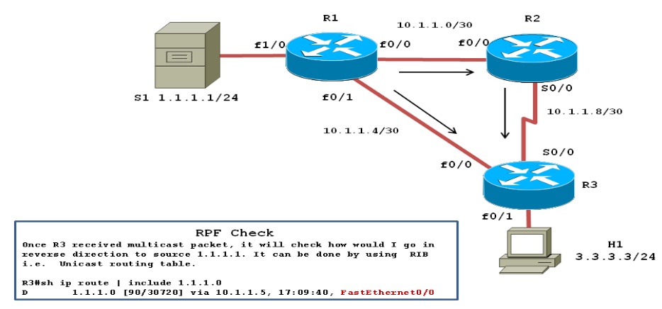
In below example multicast server S1 sends a multicast packet, with R1 flooding it to R2 and R3.R2 received its copy, and floods it as well. As a result R3 receives the same packet from two routers:
a) On its interface fa0/0 from R1.
b) On its interface s0/0 from R2.
Topology Diagram:
multicast_rpf1.jpg

Without the RPF check, R3 would forward the packet it got from R1 to R2, and vice versa, and begin the process of looping packets also with the same logic, R1 and R2 also keep repeating the process. This duplication creates multicast routing loops and generates multicast storms that waste bandwidth and router resources.
Before I dive into multicast configuration, let me share with you the initial configuration of our network. All relevant configurations are below.

R1
R2
R3
hostname R1

ip cef
!
ip multicast-routing
!
interface FastEthernet1/0
ip address 1.1.1.1 255.255.255.0
ip pim dense-mode
!
interface FastEthernet0/0
ip address 10.1.1.1 255.255.255.252
ip pim dense-mode
speed 100
full-duplex
!
interface FastEthernet0/1
ip address 10.1.1.5 255.255.255.252
ip pim dense-mode
speed 100
full-duplex
!
router eigrp 1
network 1.1.1.1 0.0.0.0
network 10.1.1.0 0.0.0.255
no auto-summary

hostname R2
!
ip multicast-routing
!
interface FastEthernet0/0
ip address 10.1.1.2 255.255.255.252
ip pim dense-mode
speed 100
full-duplex
!
interface Serial0/0
ip address 10.1.1.9 255.255.255.252
ip pim dense-mode
clock rate 2000000
!
router eigrp 1
network 10.1.1.0 0.0.0.255
no auto-summary
!


hostname R3
!
ip cef
!
ip multicast-routing
!
interface FastEthernet0/0
ip address 10.1.1.6 255.255.255.252
ip pim dense-mode
no ip route-cache
no ip mroute-cache
speed 100
full-duplex
!
interface FastEthernet0/1
ip address 3.3.3.3 255.255.255.0
ip pim dense-mode
ip igmp join-group 239.1.1.1
!
interface Serial0/0
ip address 10.1.1.10 255.255.255.252
ip pim dense-mode
no ip route-cache
no ip mroute-cache
clock rate 2000000
!
router eigrp 1
network 3.3.3.3 0.0.0.0
network 10.1.1.0 0.0.0.255
no auto-summary
!

When R3 performs the RPF check the following things will happen:
1) R3 examines the Source address of each incoming packet, which is 1.1.1.1.
2) R3 determines the reverse path interface based on its route used to forward packets to 1.1.1.1
In our case R3's route to 1.1.1.1/24 is matched, and it is lists an outgoing interface fa0/0, making fa0/0 R3's RPF interface for IP address 1.1.1.1
R3#sh ip route | beg Gate
Gateway of last resort is not set

     1.0.0.0/24 is subnetted, 1 subnets
D       1.1.1.0 [90/156160] via 10.1.1.5, 02:01:51, FastEthernet0/0
     3.0.0.0/24 is subnetted, 1 subnets
C       3.3.3.0 is directly connected, Loopback0
     10.0.0.0/30 is subnetted, 3 subnets
C       10.1.1.8 is directly connected, Serial0/0
D       10.1.1.0 [90/30720] via 10.1.1.5, 04:24:40, FastEthernet0/0
C       10.1.1.4 is directly connected, FastEthernet0/0

R3#sh ip rpf 1.1.1.1
RPF information for ? (1.1.1.1)
RPF interface: FastEthernet0/0
RPF neighbor: ? (10.1.1.5)
RPF route/mask: 1.1.1.0/24
RPF type: unicast (eigrp 1)
RPF recursion count: 0
Doing distance-preferred lookups across tables

R3#sh ip mroute | beg Interfac
Interface state: Interface, Next-Hop or VCD, State/Mode

(*, 239.1.1.1), 00:38:46/stopped, RP 0.0.0.0, flags: DCL
Incoming interface: Null, RPF nbr 0.0.0.0
Outgoing interface list:
   Loopback0, Forward/Dense, 00:38:46/00:00:00
   FastEthernet0/0, Forward/Dense, 00:38:46/00:00:00
   Serial0/0, Forward/Dense, 00:38:46/00:00:00
(1.1.1.1, 239.1.1.1), 00:00:26/00:02:37, flags: LT
Incoming interface: FastEthernet0/0, RPF nbr 10.1.1.5
Outgoing interface list:
   Loopback0, Forward/Dense, 00:00:26/00:00:00
   Serial0/0, Prune/Dense, 00:00:26/00:02:34, A

3) R3 compares the reverse path interface fa0/0 on which multicast packet arrives .If they match, it accepts the packets and forward it; otherwise ,it drops the packet .In this case ,R3 floods the packets received on fa0/0 from R1 but it ignore the packets received on s0/0 from R2.

Verification:

1) To verify we will be sending ICMP echo to group 239.1.1.1 from R1 with source 1.1.1.1.It's always safe to collect debugging logs in buffer rather than on console hence we will be debugging multicast packet and collect it in logging buffer as shown below:
R3#conf t
Enter configuration commands, one per line. End with CNTL/Z.
R3(config)#logging console informational
R3(config)#logging buffer 7
R3(config)#logging buffer 64000
R3(config)#no ip cef
R3(config)#end
*Mar 1 04:44:41.670: %SYS-5-CONFIG_I: Configured from console by console
R3#debug ip mpacket
IP multicast packets debugging is on

R1#ping 239.1.1.1 source 1.1.1.1

Type escape sequence to abort.
Sending 1, 100-byte ICMP Echos to 239.1.1.1, timeout is 2 seconds:
Packet sent with a source address of 1.1.1.1

Reply to request 0 from 10.1.1.6, 24 ms
Reply to request 0 from 10.1.1.6, 128 ms

R3#sh logging | beg Log
Log Buffer (64000 bytes):

IP(0): s=10.1.1.5 (FastEthernet0/0) d=239.1.1.1 (Serial0/0) id=19, ttl=254, prot=1, len=100(100), mforward
IP(0): s=10.1.1.1 (Serial0/0) d=239.1.1.1 id=19, ttl=253, prot=1, len=104(100), not RPF interface
IP(0): s=10.1.1.5 (FastEthernet0/0) d=239.1.1.1 (Serial0/0) id=20, ttl=254, prot=1, len=100(100), mforward
IP(0): s=10.1.1.1 (Serial0/0) d=239.1.1.1 id=20, ttl=253, prot=1, len=104(100), not RPF interface
IP(0): s=1.1.1.1 (FastEthernet0/0) d=239.1.1.1 (Serial0/0) id=20, ttl=253, prot=1, len=100(100), mforward
IP(0): s=1.1.1.1 (Serial0/0) d=239.1.1.1 id=20, ttl=252, prot=1, len=104(100), not RPF interface

From the above logs we can see that R3 forwarded the packets received on fa0/0 from R1 but it ignore the packets received on s0/0 from R2.
2) Let’s look it same with mtrace from R1 and capturing packet with the help wireshark on  R3’s interface Fa0/0 and S0/0.
R1#mtrace 1.1.1.1 3.3.3.3 239.1.1.1
Type escape sequence to abort.
Mtrace from 1.1.1.1 to 3.3.3.3 via group 239.1.1.1
From source (?) to destination (?)
Querying full reverse path...
0 3.3.3.3
-1 10.1.1.6 PIM  [1.1.1.0/24]
-2 10.1.1.5 PIM [1.1.1.0/24]
-3 1.1.1.1

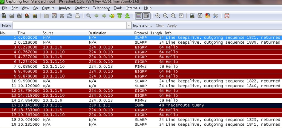
On R3’s interface fa0/0 we capture trace route query and request as mark in black box below diagram:
1.jpg
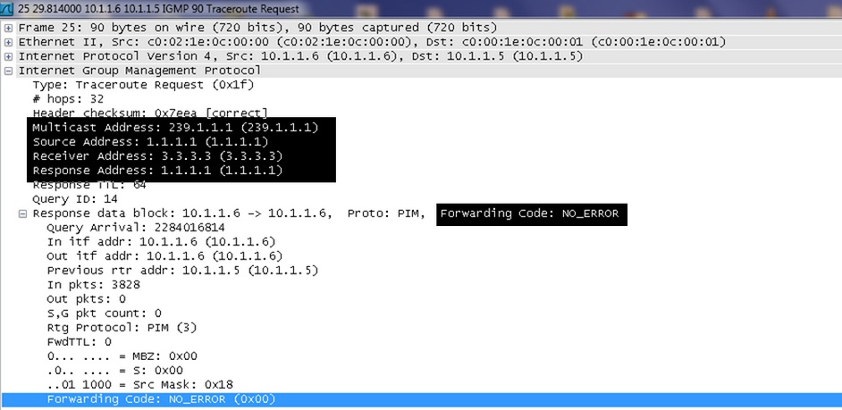
Let's open the traceroute request packet to get more detail inside view.
2.jpg
As show in above figure “FORWORDING CODE: NO_ERROR” field shows that after the router receives a multicast packet it performed an RPF check as the RPF check succeeds, the packet is forwarded.
Now let’s view capture taken on interface S0/0:
3.jpg

It is only showing trace route query not request as packets are drop due to RPF check failure.
Hence conclusion is the RPF check is a strategy by which router accept packets that arrives over the shortest path and discard those that arrive over longer routes and thereby avoid routing loops and duplication.

How Does Traceroute Work and Example's of using traceroute command

  If you are working as a network administrator, system administrator, or in any system operations team, then you might have already ...